This Bridge Looks Just Like the Others
Reinforced- and prestressed-concrete slab bridges
Reinforced-concrete slab bridges have a rigid horizontal member that serves as both the bridge deck and superstructure.
Variations of the type include cast-in-place and precast slabs, constructed using different methods.
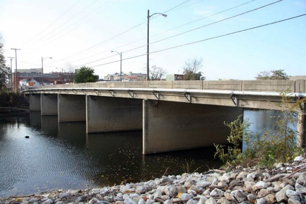
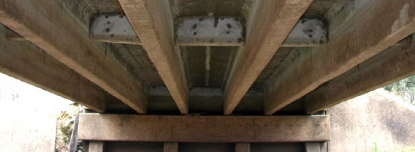
Reinforced-concrete slabs could be cast-in-place, such as this one, or precast (HAER IN-113).
(Image courtesy of Mead & Hunt, Inc.)
Reinforced cast-in-place slabs
Reinforced cast-in-place concrete slabs came into popular use during the first decades of the twentieth century. As the
name suggests, these bridges are cast on-site by pouring concrete into forms and letting it cure into the final slab. For
added strength, the earliest examples were constructed using metal reinforcement within the concrete to withstand the tension
stress produced by loads placed on the structure. This type of reinforcing was eventually supplanted by a more complex system
that included diagonal reinforcing members and rods with “mushroom heads” that provided shear (vertical) reinforcement.
The earliest cast-in-place concrete slab bridges were short, simple spans. Many States adopted standard plans for this type
that were commonly built during the 1930s and 1940s as their modest length made them easy and economical to construct. Multi-span
examples were also built, and as the length increased so did the slab thickness to withstand the load of traffic over longer
distances. Reinforced-concrete slab main span lengths generally range from about 10 to 50 feet. This bridge type remained
in use during the post-1945 period due to the simplicity of its design and construction.
Reinforced precast slabs
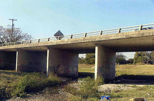
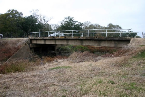
The traditional concrete slab form modernized using new prestressed-concrete methods (HAER TX-3398).
(Image courtesy of Mead & Hunt, Inc.)
Precast reinforced-concrete slabs were constructed in limited numbers during the early twentieth century but were commonly
used after World War II. Unlike cast-in-place concrete slabs, the precast version consists of separate concrete sections
cast in a mold, which are often fabricated in a casting yard using factory-like precision and methods. The individual sections
are then moved to the bridge site and placed side-by-side and connected to form a single unit. Similar to cast-in-place
reinforced-concrete slabs, metal reinforcement was embedded in the concrete during the fabrication process. Precast slabs
offered several advantages over cast-in-place slabs. By eliminating the need for on-site fabrication and associated labor
costs, benefits achieved are: faster construction time, ease of managing traffic flow during construction, and more control
over processes related to mixing, placement, and curing of the concrete. Typical lengths for spans of this type are similar
to cast-in-place slabs. Precast reinforced-concrete slabs were constructed throughout the post-World War II era.

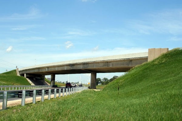
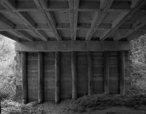
The prestressed-concrete slab serves as both the bridge deck and superstructure (HAER TX-3398).
(Image courtesy of Dietrich Floeter.)
Prestressed-concrete slabs
Prestressed-concrete slab construction, like prestressed beams and girders, began after World War II and continues to be
used. The slab serves as both the bridge deck and superstructure. Longitudinal steel strands (either pre- or post-tensioned)
are placed near the bottom of the slab and steel U-shaped stirrups are placed at regular intervals within the slab to provide
shear reinforcement. Some precast units are fabricated with circular or rectangular voids, which results in an economy of
materials and lighter overall structure. Span lengths for prestressed-concrete slabs generally range in length from 30 to
50 feet. At present, prestressed-concrete slabs are used as deck components between girders but are also used as main structural
elements on shorter spans.
Reinforced- and prestressed-concrete beam and girder bridges
Concrete beam and girder bridges consist of structural members parallel to the roadway that absorb the force of live traffic
and bridge weight. The terms girder and beam are often used interchangeably but girders are essentially large beams. Variations
are based on the shape and configuration of the reinforced-concrete beams and the fabrication method, including the process
of prestressing that became prevalent in the post-World War II period. Unlike reinforced concrete, prestressed beams require
specialized tensioning embedded in the beams that are manufactured in casting beds rather than on-site. The casting beds
were technological achievements in their own right in the early years of prestressed concrete usage since the forms could
be reused and enabled mass production of these large structural elements. The use of prestressed concrete for bridge construction
in the United States began in 1950. Standard shapes and forms for prestressed-concrete bridge members were developed by
the American Association of State Highway Officials (AASHO) and the Prestressed Concrete Institute (PCI) in the 1960s. Prestressed
concrete as a bridge-building material was widely used throughout the latter half of the twentieth century and continues
to be used today.
Standardized shapes and forms were developed for many types, including the reinforced-concrete box.
(Image courtesy of Mead & Hunt, Inc.)
The reinforced-concrete box beam, a variation of the concrete girder, features a hollow design.
(Image courtesy of Mead & Hunt, Inc.)
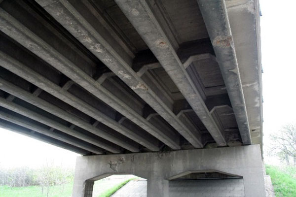
Reinforced-concrete box beams
Reinforced-concrete box beams are a variation of the concrete girder that features a hollow box design. Longitudinal voids
left in the girder are circular or rectangular and serve to decrease the beam weight and materials. The type was first introduced
in the western United States in the late 1930s. Concrete boxes offer some design flexibility in that individual box beam
units can be oriented adjacent to one another, connected using tie rods, or spaced apart to achieve larger span widths.
Span lengths typically ranged from 20 to 100 feet, with the most economical spans ranging from 40 to 75 feet. In the 1960s
standardized shapes and forms were developed. The reinforced type gradually fell out of favor and was replaced by a prestressed-concrete
variation.
![This illustration shows the concrete pouring sequence for a reinforced-concrete box beam. (Diagram courtesy of the Library of Congress, Prints & Photographs Division, HAER [HAER DC-53].)](images/this_bridge06b.jpg)
This illustration shows the concrete pouring sequence for a reinforced-concrete box beam.
(Diagram courtesy of the Library of Congress, Prints & Photographs Division, HAER [HAER DC-53].)
Reinforced-concrete tee beam
Reinforced-concrete tee beams feature a rectangular T-shaped member that supports an integral deck slab which serves as
the road surface. The integration of the beam and deck increases the bridge strength which in turn allows for increased
span lengths. As a result, concrete tee beams were touted as a better option than concrete slabs for bridges between 25
and 50 feet in length. Steel reinforcement in the tee beam consists of steel rods set into the horizontal portion that comprises
the deck (the top of the “T”) and lower vertical section of the beam (the stem). Transverse rods extend between the top
and bottom of the beam and are tied together with U-shaped hangers resulting in an integrated slab and beam.
Reinforced-concrete tee beams feature T-shaped members that support an integral deck and road surface.
(Image courtesy of Mead & Hunt, Inc.)
Many States long had standard plans for reinforced-concrete tee beams, which they updated in the postwar period.
(Image courtesy of Mead & Hunt, Inc.)
Reinforced-concrete tee beam bridges came into use during the 1910s and were constructed into the 1960s. It was one of the
earliest bridge types to be standardized by State highway departments. Span lengths for this type range between 15 and 100
feet.
Reinforced-concrete channel beams are similar to tee beams but with butting U-shaped members (HAER IA -97).
(Image courtesy of Rob Tucher.)
Reinforced-concrete channel beam
Reinforced-concrete channel beams are similar to tee beams but instead of a rectangular shaped beam, they consist of an
elongated U-shape beam that features a horizontal flat top portion and two lower vertical portions, called stems.
Channel beams are typically precast in standard lengths that range from 20 to 70 feet but can also be cast-in-place. During
bridge construction, multiple channel beams are placed side-by-side resulting in what appears to be a joint or seam along
the bottom edge of the beams where they meet; the top flanges (protruding edges) abut one another to form the roadway slab.
Steel reinforcement consists of longitudinal rods at the bottom of the stems and shear reinforcement that runs vertically
between the top and bottom of the stems. Reinforced-concrete channel beam bridges typically also have diaphragms that provide
support between the main beams, which is why they are sometimes referred to as "waffle slabs." This type was introduced
in the 1910s and later became one of the standard types used by State highway departments. Reinforced-concrete channel beams
continued to be used into the 1970s.
Prestressed-concrete I-beam and bulb-tee
Prestressed-concrete I-beams feature high tensile wires or cables embedded in the bottom flange of the beams that are stretched
(stressed, or tensioned) prior to casting and curing of the concrete.
The concrete and steel are in direct contact and once the concrete cures, the tension of the steel is released and the load
transfers to the concrete. This type of prestressing is known as pre-tensioning and results in a strong beam that effectively
balances the tensile and compressive forces of external loads and traffic. The innovative fabrication method of prestressing
beams enabled span lengths up to 150 feet.
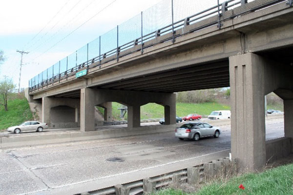
Prestressed-concrete I-beams were popular for use on the new Interstate Highway System (HAER MN-121).
(Image courtesy of Mead & Hunt, Inc.)
Prestressed-concrete I-beams have high tensile wires embedded in the bottom of the beam that transfers loading to the concrete
(HAER MN-121). (Image courtesy of Mead & Hunt, Inc.)
Another method of prestressing is post-tensioning whereby ducts (small voids) are left in the concrete members during fabrication.
After the concrete cures, reinforced steel strands are fed into the ducts and then stretched (tensioned) and secured using
anchors or another type of locking device. Concrete grout is then placed in the voids to secure the steel reinforcement.
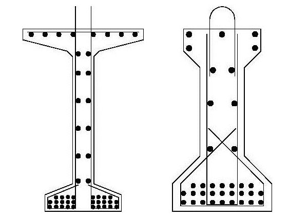
The bulb tee (left) is a variation of the prestressed I-beam (right) with flanges of different sizes, although dimensions
and designs will vary by State.
(Image courtesy of FHWA).
The bulb tee is a variation of the prestressed I-beam. Dimensions and designs vary by State but the common feature is an
I-beam with flanges of different sizes. The bottom flange on bulb tees includes the prestressed steel strands while the
top flange is wider and provides structural support for the concrete deck.
Prestressed-concrete box beam
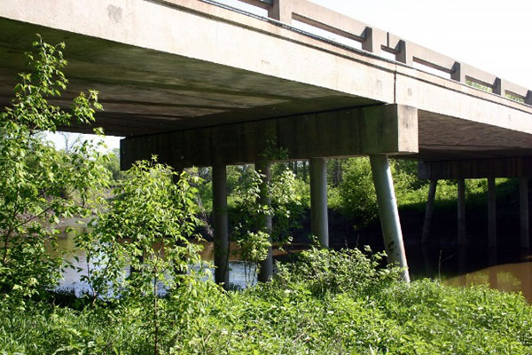
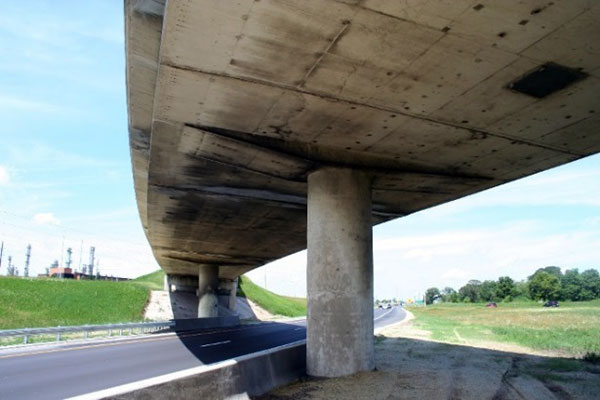
Interstate builders favored bridges where speed of construction was a priority, such as this prestressed-concrete box.
(Image courtesy of Mead & Hunt, Inc.)
Prestressed-concrete box beams are longitudinal box-shaped structural members that feature either circular or rectangular
voids that help reduce beam weight and materials. The design of box beams differ from conventional I-beams in that the top
and bottom portions of box beams act as flanges and the side walls act as webs, whereas I-beams have two flanges and a single
web. Beams were configured in several ways - either immediately adjacent to one another, immediately adjacent and connected
using a tie rod, or spread out 2 to 6 feet. Box beams range in span length from 20 to 100 feet, with the most economical
spans between 40 and 90 feet. Box beams are easily assembled and were ideal where speed of construction was a priority.
Developed in the early 1950s, prestressed box beams were built throughout the late twentieth century and are still utilized
today. Most present-day examples are built using the tie-rod configuration that offers optimum strength and stability for
the structure.
Steel multi-beam or multi-girder bridges
Steel beam or girder bridges comprise multiple steel I-beams that are either built-up or fabricated of rolled steel that
has short flanges (protruding edges) joined by a web that creates a cross section that forms the letter "I." The strength
and durability of steel I-beams increased over the course of the twentieth century as innovation in steel fabrication led
to a variety of steel beam lengths and depths. The widespread use of steel I-beams by State highway departments began in
the 1920s. The use of cantilever and continuous configurations after World War II led to increased span lengths of up to
80 feet. Steel was gradually replaced by prestressed concrete as the material of choice for bridge construction in the latter
half of the twentieth century.
Steel rolled multi-beams
Rolled beams are fabricated out of one piece of steel and the flanges (protruding edges at the top and bottom) and web (central
portion) are integral.
These bridges sometimes have transverse diaphragms spanning between the longitudinal beams. The use of cantilevered drop-in
units, which were attached to the fixed beams using notched beam seats with bearings, was an early method for achieving
greater span lengths for steel bridges. A later method involved the use of a pin and hanger mechanism that also enabled
longer spans.
The widespread use of steel rolled beams for highway bridges began in the 1920s and 1930s as State highway departments developed
standard plans for the type. Rising steel prices and the increasing popularity of prestressed-concrete beams led to a gradual
decline in use of steel rolled beams for shorter spans during the post-World War II period. However, this type provides
longer clear spans than prestressed concrete and is still utilized today, especially for spans 100 feet or less.
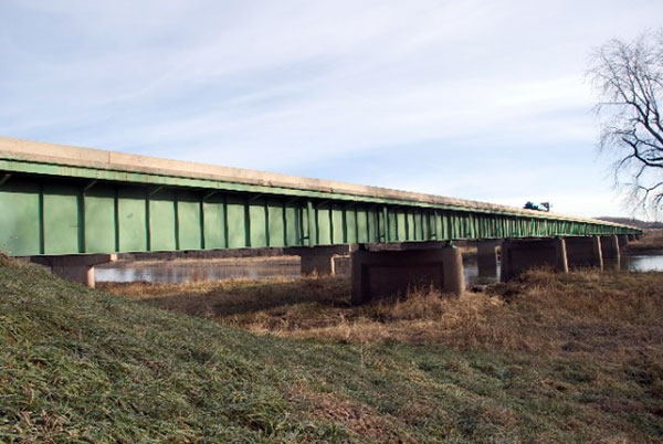
Steel beams, a long established type, were less common in the postwar period than their concrete counterparts (HAER MN-
124).
(Image courtesy of Mead & Hunt, Inc.)
Steel rolled beam bridges are still constructed today, particularly for spans 100 feet or less.
(Image courtesy of the Wisconsin Historical Society, WHI-40198.)
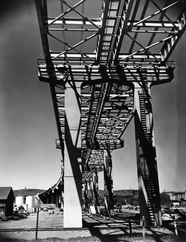
Steel fabricated (built-up) girders
Used as early as the late nineteenth century, steel fabricated or built-up girders, also referred to as plate girders, are
comprised of flanges, webs, and stiffeners that are riveted or welded together to form a single unit that is shaped like
an “I.”
The web is situated between the top and bottom flanges (horizontal plates) and is typically deep, which enables the plate
girder to extend beyond the length of a rolled beam. A series of stiffeners that lie between the top and bottom flanges
provides additional strength for the built-up girder. Main span lengths for steel built-up girder bridges generally ranged
from about 20 to 130 feet, although longer examples were also built.
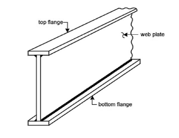
This illustration shows a beam fabricated from three pieces of steel. (Image courtesy of FHWA Bridge Inspector’s Manual,
Publication No. FHWA NHI 03-001, October, 2002.)
Steel fabricated (built-up) girders are built by riveting or welding web and flange pieces together (HAER IA-99).
(Image courtesy of Louis Berger.)
This type can be constructed as either a through girder or deck girder. In a through girder, the deck is carried between
two girders that rise above the deck and appears as a parapet wall. In deck-girder configuration, the deck is carried on
top of the girders. Steel built-up girders were more expensive to build because of the labor and cost of fabricating the
girder. The earliest examples were constructed with rivets, which were replaced by welding in the 1950s as advances in welding
techniques were applied to bridges. High-strength bolted connections became the preferred connection type in the late 1970s
but in the late 1990s welding again gained favor.
Culverts
Culverts are short spans located under roadways that drain water from one side of the road to the other. These structures
are usually less than 20 feet and typically lack railings, sidewalks, or decks. The structural unit or hydraulic opening
through which water flows in a culvert is called a cell. Multiple cells can be placed adjacent to one another to create
larger structures. Culverts are typically prefabricated by manufacturers and shipped to the site, but State Departments
of Transportation also developed standard plans in various sizes to increase efficiency of design and construction. After
World War II, the Interstate Highway program served as a powerful catalyst for new innovations and fostered developments
in advanced drainage techniques, including culvert design and materials.
Culverts are commonly constructed of steel or concrete and have two basic forms: box and pipe. Box culverts have a square
or rectangular shape while pipe culverts provide an opening by means of a round tube shape. Several factors influence the
choice of culvert material, including site conditions, available funding, and even the marketing efforts of culvert distributors,
although American Association of State Highway Officials specifications eventually replaced manufacturer’s catalogues as
the design source for culverts. Culverts can be built with or without headwalls, which are located at the end of a culvert
to divert flow, protect fill, and serve as a retaining wall.
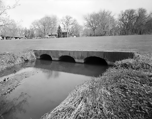
Concrete box culverts
Some or all of the four sides of concrete box culverts can be reinforced with steel rebar. Span lengths typically range
between 5 and 50 feet, with the latter length often consisting of multiple cells.
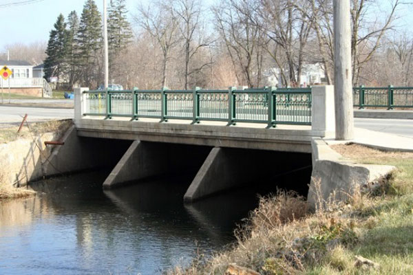
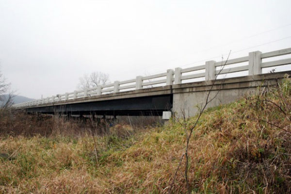
The addition of an aesthetic railing to a concrete box culvert was unusual during the postwar period (HAER MN-125).
(Image courtesy of Mead & Hunt, Inc.)
Builders used precast box units manufactured off-site to construct concrete box culverts (HAER MN-125).
(Image courtesy of Mead & Hunt, Inc.)
Prior to World War II, most concrete culverts were cast-in-place, meaning they were monolithic structures, poured in a pre-made
form so all sides of the culvert formed a single unit without construction joints. After World War II, the use of cast-in-place
concrete culverts declined as these were replaced by precast concrete box units that were manufactured off-site.
Concrete pipe culverts were available in a variety of shapes to accommodate site conditions (HAER WI-118).
(Image courtesy of Dietrich Floeter.)
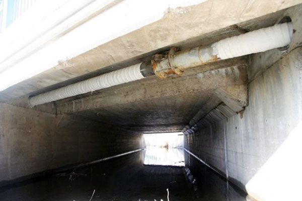
Concrete pipe culverts
Concrete pipe culverts are prefabricated from reinforced concrete and manufactured in various sizes as large as 12 feet
in diameter. The shape of concrete pipe culverts is determined by the peak flow of the channel.
Circular shapes are hydraulically and structurally efficient under most conditions and are the most common type of concrete
pipe culvert. Elliptical shapes are typically used when conditions limit horizontal or vertical clearance. Concrete pipe
culverts were utilized throughout the post-World War II period and are still in use today.
Steel pipe culverts
Steel pipe culverts are tube-like units that are typically corrugated and come in a variety of sizes to provide continuous
flow for the entire width of the roadway. Like their concrete counterparts, steel pipe culverts were prefabricated and can
be easily shipped to construction sites due to their light weight.
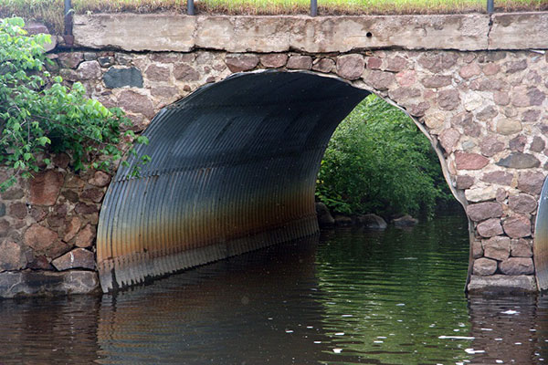
Multi-plate arches feature corrugated-metal bolted together to form the arch.
(Image courtesy of Mead & Hunt, Inc.)
Steel pipe culverts are also easy to install, reducing costs and labor, and their low maintenance makes them ideal for sluggish
waterways or small rivers. Multi-plate was a galvanized, corrugated-iron product fabricated in curved segments that were
bolted together in the field to form an arch and anchored by concrete headwalls and abutments. In the mid-1960s a more hydraulically
efficient option was introduced—the corrugated metal pipe arch—which featured a flat bottom, circular top, and sharp radius
corner plates that were bolted together in the field.
The pipes were also galvanized using traditional coatings. Small crossings using steel pipe culverts were constructed in
the post-World War II period and are still installed today.

